DESCRIPTION
The WEO12832W#SP3N00000-FC is a 0.91-inch OLED display module with a 128x32 dot matrix and integrated CH1120 driver IC. Designed for compact systems, this OLED 0.91-inch display is optimized for applications where mechanical depth, power efficiency, and clear monochrome rendering are key constraints. It supports 4-bit grayscale, offering more flexibility for UI expression compared to traditional 1-bit OLED modules.
The OLED display 0.91 128x32 operates at 3V logic power and offers SPI and I2C interfaces for seamless integration with most MCU platforms. The module features a wide viewing angle of 160° (H/V) and an extensive operating temperature range from –40°C to +80°C, ensuring stable performance in both consumer and industrial environments.
Key Characteristics
- 0.91" COG OLED module
- 128×32 resolution
- CH1120 driver IC
- 4-bit grayscale support
- Interface options: SPI / I2C
- Logic voltage: 3V
- Display color: White or Yellow
- Viewing angle: 160° horizontal / 160° vertical
- Operating temperature: –40°C to +80°C
- Ideal for low-power, space-limited designs
Recommended Applications
With its compact
OLED 0.91-inch dimensions and energy-efficient design, the WEO12832W#SP3N00000-FC is ideal for:
- Wearable and portable devices: fitness trackers, compact indicators, wrist-type devices
- Portable medical equipment: handheld meters, diagnostic accessories
- Test and measurement tools: multimeters, data loggers, small instrumentation panels
- IoT nodes and compact controllers: sensors, control modules, smart home handheld units
- Battery-powered handheld devices
DRAWING
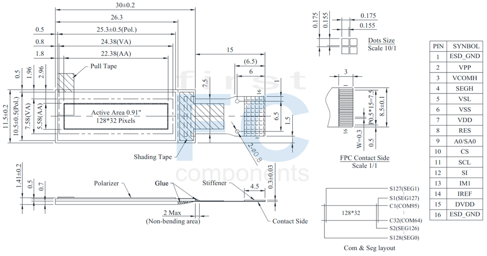
SPECIFICATIONS
General Specification
| Item | Dimension | Unit |
|---|
| Dot Matrix |
128 × 32 Dots |
- |
| Module dimension |
30.0 × 11.5 × 1.41 |
mm |
| Active Area |
22.38 × 5.58 |
mm |
| Pixel Size |
0.155 × 0.155 |
mm |
| Pixel Pitch |
0.175 × 0.175 |
mm |
| Display Mode |
Passive Matrix |
| Display Color |
Monochrome |
| Drive Duty |
1/32 Duty |
| Gray Scale |
4 bits |
| IC |
CH1120 |
| Interface |
4-wire SPI,I2C |
| Size |
0.91 inch |
Absolute Maximum Ratings
| Parameter | Symbol | Min | Max | Unit |
|---|
| Supply Voltage for Logic |
VDD |
-0.3 |
3.5 |
V |
| Supply Voltage for Display |
VPP |
-0.3 |
15.0 |
V |
| Operating Temperature |
TOP |
-40 |
+80 |
°C |
| Storage Temperature |
TSTG |
-40 |
+85 |
°C |
Electronical Characteristics
DC Electrical Characteristics
| Item | Symbol | Condition | Min | Typ | Max | Unit |
|---|
| Supply Voltage for Logic |
VDD |
- |
1.65 |
3.0 |
3.5 |
V |
| Supply Voltage for Display |
VPP |
- |
8.0 |
9.0 |
9.5 |
V |
| Input High Volt. |
VIH |
- |
0.8×VDD |
- |
VDD |
V |
| Input Low Volt. |
VIL |
- |
VSS |
- |
0.2×VDD |
V |
| Output High Volt. |
VOH |
- |
0.8×VDD |
- |
VDD |
V |
| Output Low Volt. |
VOL |
- |
VSS |
- |
0.2×VDD |
V |
| Display 50% Pixel on |
IPP |
VPP=9V |
- |
3 |
6 |
mA |
Interface Pin Function
| No. | Symbol | Function |
|---|
| 1 |
ESD_GND |
This pin should be connected to GND. |
| 2 |
VPP |
OLED panel power supply.
Connect to capacitor. It could be supplied externally. This is the most positive voltage supply. |
| 3 |
VCOMH |
This is a pin for the voltage output high level for common signals.
A capacitor should be connected between this pin and VSS. |
| 4 |
SEGH |
This is a segment pre-charge voltage.
A capacitor can be connected between this pin and GND if necessary. When external capacitor is not used, this pin should be kept NC. |
| 5 |
VSL |
Discharge voltage level pad.
This pad should be connected to resistor and diode externally. |
| 6 |
VSS |
Ground for logic and analog. This pin should be connected to GND externally. |
| 7 |
VDD |
Power supply for logic. |
| 8 |
RES |
This is a reset signal input pin. When RES is set to “L”, the settings are initialized. The reset operation is performed by the RES signal level.
This pin internal pull high. |
| 9 |
A0/SA0 |
This is the Data/Command control pin that determines whether the data bits are data or a command.
In I2C interface, this pad serves as SA0 to distinguish the different address of OLED driver. |
| 10 |
CS |
This pin is the chip select input. When CS = “L”, then the chip select becomes active, and data/command I/O is enabled. |
| 11 |
SCL |
The serial clock input. |
| 12 |
SI |
The serial data input. |
| 13 |
IM1 |
MCU bus interface selection pins.
|
| 14 |
IREF |
This is a segment current reference pin.
A resistor should be connected between this pin and GND. |
| 15 |
DVDD |
This pin is for regulator circuit.
A capacitor should be connected between this pin and GND if necessary. When external capacitor Is not used, this pin should be kept NC |
| 16 |
ESD_GND |
This pin should be connected to GND. |
Specifiche di prodotto
|
Size
|
0.91" |
|
Resolution
|
128x32 |
|
Active Area (mm)
|
22.38x5.58 |
|
Dot Size
|
0.15x0.15 |
|
Polarizer
|
Glare |
|
Color
|
White |
|
Power supply
|
3V |
|
Display Interface
|
SPI/I2C |
|
Display IC
|
CH1120 |
|
Constructive Structure
|
COG |
|
Frame
|
No |
|
Touch Panel
|
No touch |
|
O. Temperature (°C)
|
-40~80 |
|
Data Connection
|
FPC for ZIF Connector |
|
Pin Nr.
|
16 |
|
Pin Pitch
|
0.5mm |
|
Preferred - Not Preferred
|
Preferred |