Functional description
Smart Display can be used to display the coordinate, status and data information provided by the connected HOST device. Customers can configure the position coordinates they want to display in normal operation mode.
The Display is designed to be easily connected to a controller network, and to use the register type of Holding Register
Splash Screen
The default splash image is shown below.
This product is produced as a generic product. If you require a custom splash image for your application, contact us to discuss.
Acquisition of Displayed Data
Smart Display uses the Modbus protocol to get and send the data.
On Config mode, customers can set the coordinates or type of objects; On Display mode, customers can send and get data of objects.
Configuring the Display
Winstar Smart Display RS-485 series offers an out-of-the-box Modbus development experience that will lower customers' development costs and speed time-to-market expectations.
The Smart Display can use wide-temperature are designed to support control applications in harsh operating conditions, which designed to be connected to a variety of different situation combinations, such as automotive, marine, power generation and oil-and-gas.
The Smart Display can use wide-temperature are designed to support control applications in harsh operating conditions, which designed to be connected to a variety of different situation combinations, such as automotive, marine, power generation and oil-and-gas.
The Smart Display comes with standard UI objects to get customers project off the ground quickly. If customers need custom UI objects support, our engineers are here to help. Send over your contents in PNG/JPG format, we will send over a new set of UI objects within 3~5 working days
The Smart Display is defined as a slave device, which is controlled by master device via RS-485 command to render display content on the display screen and return touch event data with protocol objects.
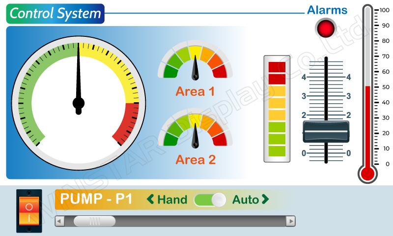
Example Screen Layout (Industry application)
The screen layout described in this section is intended to demonstrate the settings of screen items that can be used in a industry application situation.
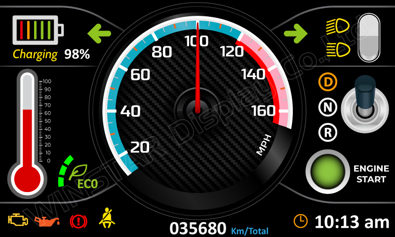
Example Screen Layout (Vehicle automotive)
The screen layout described in this section is intended to demonstrate the settings of screen items that can be used in a vehicle automotive situation.
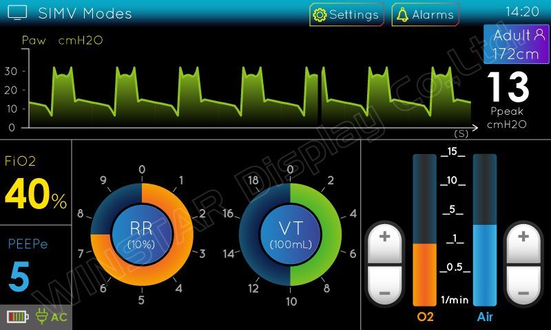
Example Screen Layout (Medical application)
The screen layout described in this section is intended to demonstrate the settings of screen items that can be used in a Medical application situation.